

Introduction
Materials and Methods
Multi-RLS based all-wheel steering control framework for path tracking
Result and Discussion
Conclusion
Introduction
Mobility is being utilized in various fields, and is particularly utilized in transportation. Recently, the demand for MaaS (Mobility as a Service) is expected to continue to increase, and various services utilizing autonomous mobility are being developed in the agricultural sector. Research in the automobile industry is being developed to provide services to urban residents, but in the agricultural sector, the primary goal is to liberate farmers from hard labor, and the concept of cooperative mobility is being developed. In the future, robots will be attached to mobility to enable collaboration in monitoring and harvesting.
The specific purposes of the mobility service system are classified into five categories (Xiang and Koo, 2023). First, the last-mile area for purposes such as transfers, taxis, school buses, and other large-scale transportation delivery. Second, the safety technology area for special purposes such as emergency, medical, firefighting, and construction. Third, the autonomous driving technology area for commercial purposes such as logistics. Fourth, the commercialization area for living services such as business, food, hotel, health, and leisure. Fifth, the customization area for customized purposes such as passenger car cross-country and camping. In the fifth customization area, the agricultural sector seems to require diverse development. Therefore, it seems advantageous to approach agricultural mobility with the concept of PBV (Purpose Built Vehicle). Mobility development in the agricultural sector requires adaptability and drivability in various environments, so it requires adaptability to off-road and on-road conditions and performance optimization of the steering system and friction power transmission system of the mobility system. A study on the form factors required in various fields suggested a specific design that considers the loadability and usability of cart-based micromobility that focuses on the movement of cargo rather than individual movement (Park, 2022). The study that considers the loadability and usability with the characteristics of agricultural mobility is needed for working and driving efficiency of the agricultural mobility under various road conditions.
A number of studies on electric steering and autonomous driving in mobility have been conducted. In the field of mobility, there are a number of studies on electric steering and autonomous driving. The problem of parameter identification of reluctance motors was solved by using the recursive least squares algorithm that considers the convergence of inductance parameters for current and resistance of autonomous steering devices as constraints (Yang et al., 2021). To reduce steering error, the errors in the parallel circuit were detected and the line distance and error resistance of the circuit were estimated to detect the errors (O’Shea et al., 2019). The parameters and state information of the steering were estimated using the unscented Kalman filter and the recursive least squares method to estimate the influence of noise and uncertainty on the system(Singh et al., 2020). As a methodology to improve the mobility safety of industrial systems and reduce system maintenance costs, a condition monitoring algorithm was proposed to detect the performance degradation of system models based on experimental data (Zhao et al., 2023). When an electric mobile vehicle for high-altitude work in a horticultural facility turns, the overturning conditions were simulated by considering the moving speed and center of gravity, and a motion analysis was performed on the steering and return speed of the front wheels according to the driving speed (Lee et al., 2022). In order to reduce the performance degradation due to data noise in a sensor data-based monitoring system, a learning-based classification algorithm combining CNN and LSTM was proposed, and research was conducted to secure stable and reliable data. In accordance with the changes in existing studies, a parameter estimation method using RLS was utilized, and a condition monitoring method was developed based on sensor data or learning data (Dang, 2020). Since RLS has a limitation that the monitoring performance deteriorates depending on the change in the application system, a vehicle condition estimation method that combines RLS with a variable forgetting factor and an adaptive iterative extended Kalman filter was proposed (Chen et al., 2024). In order to effectively utilize electric mobility in smart farms, a scissor mechanism and dynamic behavior analysis were performed using Recurdyn (Park et al., 2022).
Previous studies have often required highly reliable system data or focused primarily on hardware structures and specific mechanical analyses. In contrast, this study designed an algorithm that enables control using only state errors and control inputs, while allowing the level of rear-wheel steering engagement to be adjusted, thereby ensuring applicability even in smart farm environments with spatial constraints.
In this study, all-wheel steering algorithm for path tracking of mobility in smart farm has been developed based on ecursive least squares (RLS) method. The error dynamics used for the RLS algorithm has been designed using control error, coefficient, and control input. It is designed that the coefficients in error dynamics are estimated and it is used to compute the front and rear wheel angles in real-time based on Lyapunov direct method. To adjust the level of engagement of the rear wheel control input, parameter of reduction gain for rear wheel control input has been self-tuned using yaw angle error of mobility. The performance evaluation has been conducted by co-simulation of Matlab/Simulink and CarMaker software under path tracking scenarios in cases of with gain self-tuning and without self-tuning.
Materials and Methods
Multi-RLS based all-wheel steering control framework for path tracking
Fig. 1 shows the overall block diagram for all-wheel steering algorithm for path tracking of mobility in smart farm. The control algorithm consists of three blocks such as Waypoint-based path error derivation, Multi-RLS for coefficient estimation, and Control input derivation blocks.
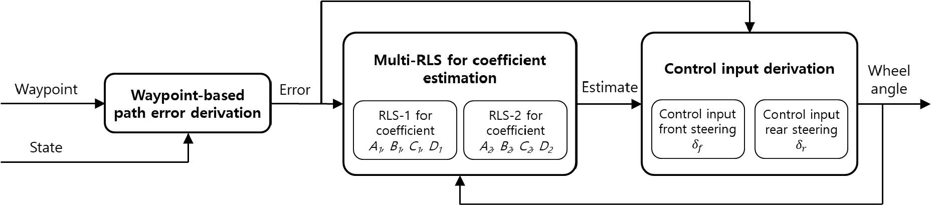
In the waypoint-based path error derivation block, the generated waypoint and mobility state are used to derive the path errors such as preview lateral and yaw angle errors. The derived path errors are used in the Multi-RLS for coefficient estimation block to estimate coefficients in the error dynamics based on two RLS algorithms. Based on the estimated coefficients, front and rear wheel angles are computed for path tracking in the control input derivation block.
The path error-based first order differential error dynamics has been designed with some coefficients to determine front and rear wheel angles of smart farm mobility. The following equations are the designed error dynamics using preview lateral() and yaw angle() errors.
Where, and are front and rear wheel angles, respectively. A, B, C, and D are coefficients in error dynamics and estimated in real-time by recursive least squares with multiple forgetting (Vahidi et al., 2005). To derive control wheel angles for path tracking of mobility, the Lyapunov candidate function has been designed as follows with one condition.
Using the designed cost function, the wheel angle inputs have been derived based on the Lyapunov direct method with asymptotic stability condition. The above cost function has been applied to each error for derivation of front and rear wheel angles. The following equations are the applied asymptotical stability condition and derived wheel angles for path tracking.
In this study, it is designed that the reduction gain for rear wheel steering is self-tuned using yaw angle error to adjust the level of engagement of the rear wheel steering input. The following equation (7) is the yaw angle error-based function for self-tuning of the reduction gain used for rear wheel angle control in equation (6).
The yaw angle error and its time derivative are used to calculate the reduction gain with a minimum value. Based on a performance evaluation using a trial-and-error methodology, the coefficients A and B were set to 200 and 10, respectively, and the minimum value was set to 0.5. In future work, the parameter determination method will be further refined based on parameter optimization theory. In this study, a path generation algorithm for path tracking was designed to generate waypoints by utilizing smart bed and mobility parameters. Fig. 2 shows the overall block diagram of the path generation algorithm, which consists of two stages: straight path generation and curved path generation.
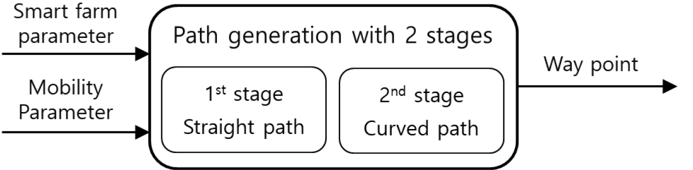
In the 1st stage, a straight road segment optimized for the smart farming environment is generated using parameters from both the smart farm and the mobility system. In the second stage, curved road segments are generated based on the same two sets of parameters. During this stage, if the minimum turning radius of the mobility system is greater than the curvature of the input path, the input curvature is adjusted to match the minimum turning radius. By iteratively repeating these two stages, continuous waypoints for the entire path can be generated. Fig. 3 shows the generated waypoint based on the designed path generation algorithm and it has been used for performance evaluation of the proposed all-wheel steering control algorithm.
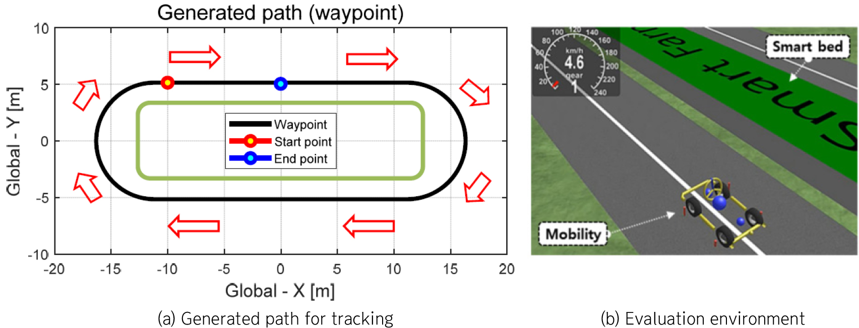
The green and black lines in Fig. 3 are the outline of smart bed and the generated waypoint, respectively. The start and end points have been explicitly defined as indicated in the Fig. 3. The red line arrows represent the driving direction of the mobility around smart bed. Table 1. shows the used mobility parameters such as mass, track width, wheel base, and overall length.
Table 1.
Mobility parameters applied to performance evaluation.
| Item | Unit | Value |
| Mass | kg | 230 |
| Track width | m | 1.26 |
| Wheel base | m | 1.35 |
| Overall length | m | 2.29 |
The performance evaluation was conducted under scenario that the mobility tracks the generated waypoint one time. The two cases of with self-tuning and without self-tuning are compared and analyzed to show the main contribution of the study.
Result and Discussion
In this study, a virtual performance evaluation environment was constructed on Matlab/Simulink and CarMaker software. The smart bed was modeled as a rectangular cuboid with dimensions of about 22.35 meters in length, 0.3 meters in width, and 1meter in height, and this model was applied to the simulation environment to evaluate the proposed algorithm. To construct a driving path around the smart bed, waypoints were placed at 5 meters intervals along the path surrounding the bed, and each segment between waypoints was interpolated at a resolution of 0.1 meters. Fig. 4 shows the evaluation results of mobility path tracking.
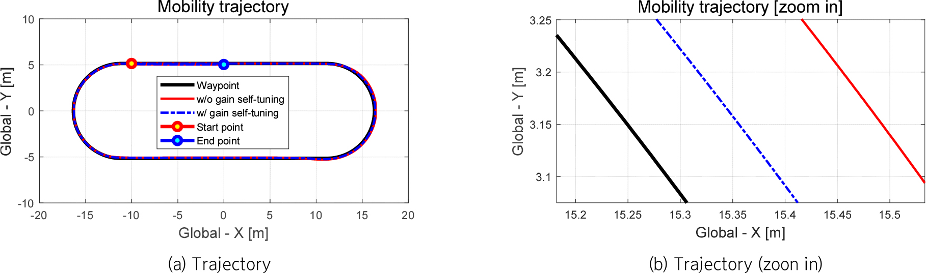
The results in Fig. 4 shows the reasonable path tracking performance for all cases and it is observed that the case of with gain self-tuning can track the waypoint more closely than the case of without gain self-tuning. Fig. 5 shows the front and rear wheel angles of mobility.
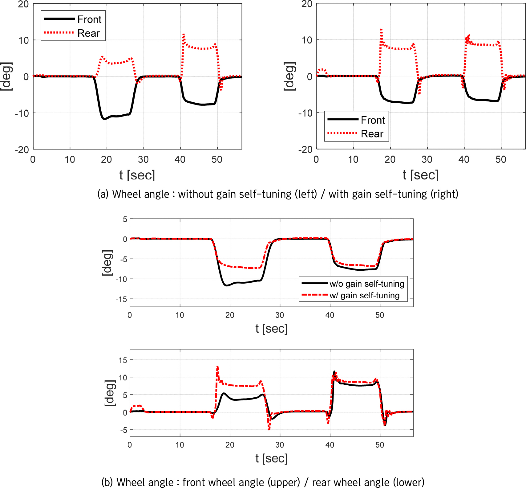
In the Fig. 5, it is found that the rear wheel angle in case of with gain self-tuning is engaged by yaw angle-based self-tuning algorithm more than in case of without gain self-tuning. Fig. 6 shows the longitudinal velocity profiles corresponding to two performance evaluation cases.
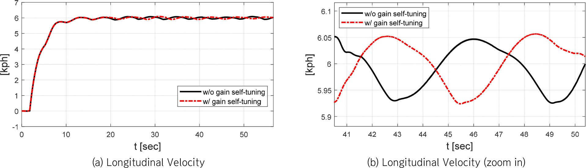
It was shown that there is not relatively large difference of the longitudinal velocity between evaluation cases. Fig. 7 and 8 shows the lateral and yaw angle error at mass center of mobility, respectively.
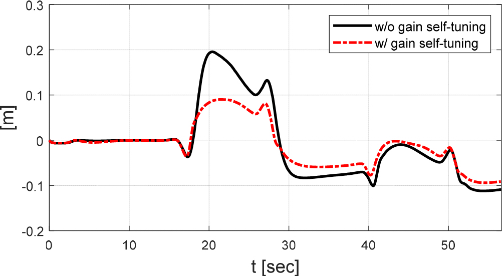
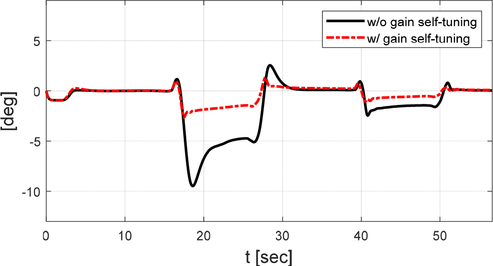
In case of with gain self-tuning, it was generally observed that the magnitude of lateral and yaw angle errors is relatively smaller than the case of without gain self-tuning. It was also observed that the lateral error oscillations were reduced when the rear wheel angle is engaged with gain self-tuning. Based on Fig. 7 and 8, it was confirmed that the lateral error is maintained within about 0.2 m and the yaw angle error is maintained within about 2 deg. Fig. 9 presents the reduction gain self-tuned by the yaw angle error-based self-tuning algorithm.
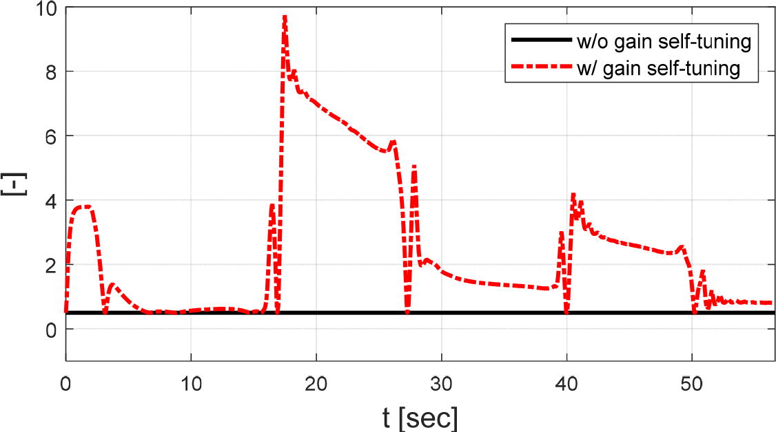
The reduction gain in case of without self-tuning is set to 0.5 and it was used as minimum value of the self-tuning function to adjust the level of rear wheel angle engagement. The result in Fig. 9 indicates that the self-tuning algorithm can adjust the reduction gain based on the designed function for rear wheel angle to reduce the yaw angle error of mobility. Fig. 10 shows the real-time estimated coefficients A, B, C, D in error dynamics.
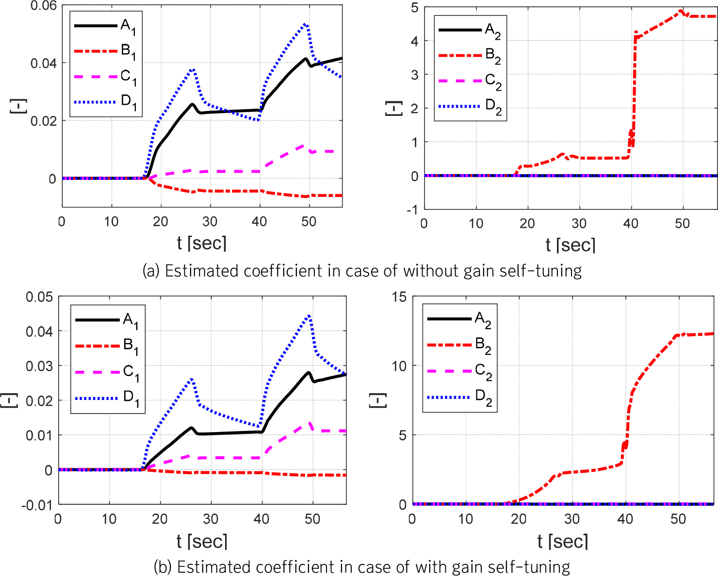
In Fig. 10, it was observed that there is relatively large difference of coefficients A1, B1, and B2 between performance evaluation cases of without self-tuning and with self-tuning.
Conclusion
The RLS based all-wheel steering algorithm for path tracking of mobility was proposed in this study with gain self-tuning. Path generation algorithm considering smart bed was designed based on mobility parameters. The path error-based error dynamics was designed and the coefficients in dynamics were estimated by recursive least squares with multiple forgetting in real-time. To adjust the level of rear wheel engagement, yaw angle error-based self-tuning algorithm of reduction gain for rear wheel angle was designed. For performance evaluation of the proposed algorithm, co-simulation technique of CarMaker and Matlab/Simulink software was used. The evaluation results showed that the case of with gain self-tuning can track the generated path with more smaller path errors than the case of without gain self-tuning. Although the proposed control algorithm showed the reasonable performance evaluation results, there is still an issue that left and right wheel angles of the mobility are same in the current step. Therefore, development of an independent steering control algorithm with improvement of the stability of the recursive least squares algorithm and optimization of parameters used for algorithm with optimization theory are considered as a future works. In actual smart farm environments, because the GPS data acquisition is not easy, it is necessary to employ tracking lanes or guiding structures in smart farm for reliable path tracking. Accordingly, future research will focus on enhancing the algorithm by utilizing sensors such as cameras to perceive paths within agricultural facilities, thereby enabling indoor autonomous navigation.
