

Introduction
Materials and Methods
3-RPS Parallel System
Self-balancing Control System
Kinematics of the 3-RPS Parallel System
Simulation Procedure
Outdoor Experiment
Result
Simulation Test
Indoor Static Test
Outdoor Dynamic Test in Uphill Road
Outdoor Dynamic Test in Bump-Downhill Road
Limitation and Future Work
Conclusion
Introduction
With the increasing scarcity of global agricultural labor and the continuous improvement in agricultural resource utilization, agricultural production efficiency has significantly decreased (Daoliang and Zhen, 2020). Consequently, the application of robotic technology in agriculture has become particularly important (Billingsley et al., 2008). Historically, most agricultural robots were adapted from industrial applications, designed to operate in highly controlled environments where nearly all variables are known. However, this approach is impractical for real agricultural settings, which are inherently dynamic and unstructured, in contrast to the structured nature of industrial environments. Therefore, current research focuses on developing intelligent machines capable of autonomously performing operations and activities in unstructured or semi-structured environments (Ting et al., 1996).
Considering that agricultural machinery typically operates on uneven terrain, enabling agricultural robots for autonomous or remote operation to navigate different surfaces while maintaining operational capabilities poses a significant challenge (Tarokh et al., 2013). Recently, researchers have predominantly focused on robot autonomous navigation (Xie et al., 2023) and vehicle configuration on sloped terrain (Vidoni et al., 2015). However, there has been limited attention to ensuring the stability of the robot’s cargo platform. Tawfeeq et al. (2022) devised a self-balancing mechanism utilizing dual motors to regulate angular adjustments across two axes, facilitating level transit across rugged landscapes. Similarly, Simon (2023) leveraged a two-wheeled balance mechanism to sustain cargo equilibrium during greenhouse transportation. Although these studies achieved success in controlled environments, further research is needed to address the challenges of scaling up these platforms for balancing robots in real-world agricultural applications. Likewise, Zhang et al. (2023) engineered a balance mechanism that uses prismatic-revolute flexible joints along legged robots to maintain the transport platform’s level posture. However, mounting mechanisms on individual legs to stabilize the platform can lead to inefficiencies. The balancing system required to handle the entire weight during operation adds complexity and potentially reduces overall efficiency.
The 3-RPS mechanism is a closed kinematic chain with three limbs, comprising a set of revolute-prismatic-spherical joints and providing 3 degrees of freedom of motion: translation along the z-axis, and rotation about the x and y-axes, respectively (Nigatu et al., 2021). Recently, many researchers have focused on the design and development of the 3-RPS mechanism due to its numerous advantages, leading to its wide application in various research fields. Bibo-Pérez et al. (2022) designed a 3-RPS parallel manipulator for high tracking accuracy in solar tracking systems, evaluating it in a simulation environment. Desai and Muthuswamy (2021) presented a generalized analytical approach to forward and inverse kinematics and workspace analysis of three degrees of freedom for the 3-RPS mechanism. Lv et al. (2023) proposed a controller design concept with gravity compensation to improve control performance for this mechanism. However, relatively few studies have explored implementing this type of mechanism in real-world applications, especially in agricultural environments. Notably, existing solutions often encounter issues such as suboptimal platform space utilization, inadequate load capacity, and compromised structural integrity, which diminish the stability and versatility of balance transport platforms. Addressing these challenges, this research proposes a balance transport platform underpinned by the 3-RPS parallel mechanism, optimizing level transit while ensuring ample space utilization and load-bearing efficiency.
Overall, this study aims to develop a balance control system that can maintain the evenness of a cargo platform for an agricultural mobile robot in sloped environments. The specific objectives are: (1) deploying a 3-RPS mechanism-based system to stabilize cargo over rough terrains, (2) applying ADAMS and MATLAB Simulink for simulation purposes, corroborated by an IMU (Inertial Measurement Unit) and ROS (Robot Operating System) validations, and (3) testing the 3-RPS mechanism equipped with a mobile robot in sloped agricultural environments.
Materials and Methods
3-RPS Parallel System
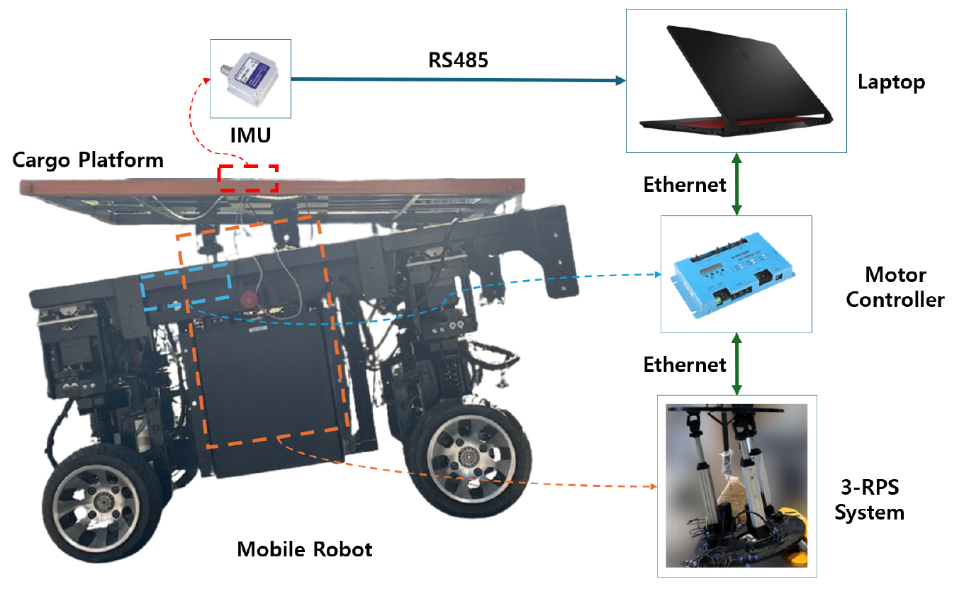
An agricultural transport robot is used to carry agricultural products, such as harvested fruits and vegetables, in orchards and uplands. The cargo balance platform of the agricultural transport robot was designed to enhance stability and mobility. As shown in Fig. 1, a 3-RPS parallel system was constructed using three parallel linear cylinders (LT75, Shenzhen DGR Electric Cylinder Technology Co., Ltd., China) equipped with servo motors (Voltage 48 V, Power 750 W, Rated torque 2.37 N·m). The stroke length and maximum allowable force of the linear cylinders are 30 cm and 3.8 kN, respectively. This system was integrated under the cargo platform of a mobile robot equipped with a four-wheel independent steering system, providing an efficient transportation solution for operations in narrow agricultural fields. The dimensions of the cargo platform are 1,600 mm in length and 1,200 mm in width. During movement, the platform can adjust its rotation angle up to 14.5° on both the X and Y axes, ensuring that it remains level on uneven terrains. An IMU (LPMS-IG1, LP-RESEARCH, Japan) with a resolution of <0.01°, accuracy of <0.3° (static), and a sampling frequency of 100 Hz was mounted on the center of the bottom surface of the cargo platform to measure its pose. A laptop computer (Intel® Core™ i7-11800H processor, 16GB system memory) installed with Ubuntu and ROS was used to collect the pose data and control the platform.
Self-balancing Control System
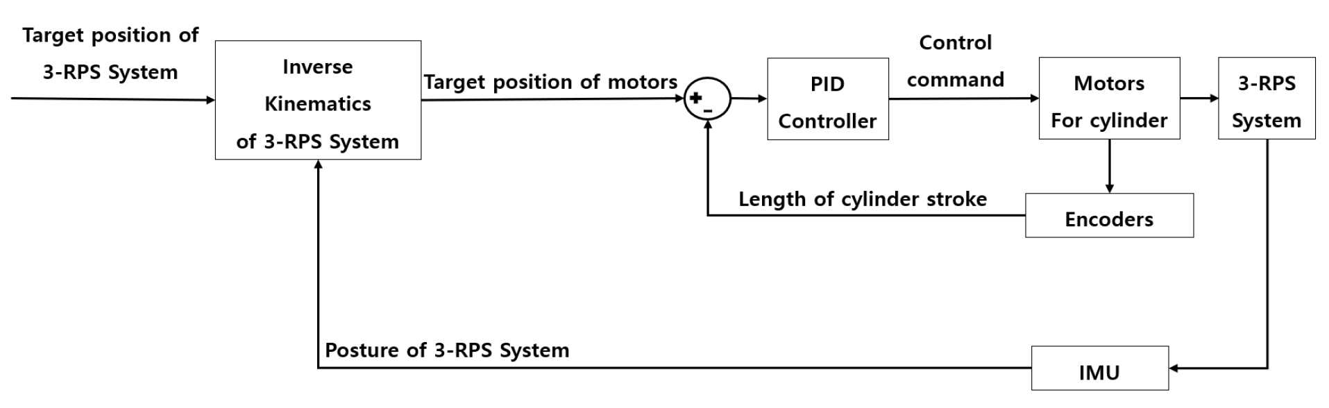
To maintain the balance of the cargo platform during the transportation of agricultural products, the initial step involves setting the target positions of the linear cylinders in the 3-RPS system. To keep the platform horizontal, the target posture is consistently set to zero. The target posture, along with the current posture obtained from an IMU sensor mounted on the cargo platform, is input into an inverse kinematics solver to determine the target positions for each linear cylinder. These target positions are then fed into a PID controller. The control commands generated by the PID controller are subsequently transmitted to the cylinder motors to adjust the 3-RPS system to the desired posture.
A feedback loop is established by re-acquiring the current posture of the 3-RPS system via the IMU sensor and the positions of the linear cylinders through encoders installed on them. This information is reintegrated into the inverse kinematics solver, thereby forming a closed-loop system for continuous balance control. Similarly, the PID component also constitutes a closed-loop system, where the actual lengths of the cylinders obtained from their encoders are fed back into the PID controller to enhance the precision and effectiveness of the balance control system. The schematic diagram of the balance control system is illustrated in Fig. 2.
Kinematics of the 3-RPS Parallel System
For the inverse kinematics calculations, coordinate systems of Oa-xayaza for the upper platform and Ob- xbybzb for the lower platform of the 3-RPS system are first established (Fig. 3). The hinge connections of the upper platform to the driving rods are designated as A1, A2, and A3. The center of the triangle formed by these three points is taken as the origin Oa of the Oa-xayaza system, with the x-axis and y-axis aligned in the direction of A1 and A2 from Oa respectively. The z-axis is aligned to be perpendicular to the upper platform surface. Similarly, the connection points on the lower platform are labeled as B1, B2, and B3, with the center (Ob) of the triangle formed by these three points in Ob- xbybzb system. The x-axis and y-axis align with the directions of B1 and B2 from Ob, and the z-axis is perpendicular to the lower platform surface.
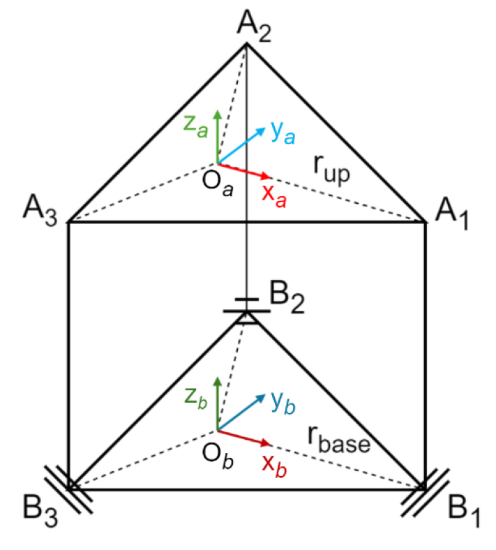
Based on the established coordinate system, the position of A1, A2, A3 and B1, B2, B3 in the upper platform’s coordinate system Oa-xayaza and in the lower platform’s coordinate system Ob- xbybzb, respectively, are expressed as Eq. (1) and Eq. (2):
Where, rup and rbase denote the radii of the circle on which the hinge connection points of the upper and lower platform are located, respectively.
A rotation matrix can be obtained using Eq. (3):
The angles , , and represent the rotation around the z-axis, y-axis, and x-axis, respectively. We utilize the IMU sensor mounted on the 3-RPS system to determine these rotational angles. Based on these measurements, the current rotation matrix RC of the cargo platform is established. With this rotation matrix (RC), the current positions of the vertices at the upper platform, denoted as A1_C, A2_C, and A3_C, are calculated using Eq. (4):
Subsequently, by setting the target angles of the 3-RPS system, we obtain the target rotation matrix, denoted as . With this rotation matrix , we also calculate the required positions of A1_T, A2_T, A3_T for the vertices of A1, A2, and A3 on the upper platform to achieve the target angles of the 3-RPS system using Eq. (5):
Next, we calculate the lengths of the current linear cylinders (, , ) and the target lengths (, , ) using Eq. (6) and (7):
Where, , , are the , , coordinates of point , respectively. , , are the , , coordinates of point , respectively. , , are the , , coordinates of point respectively.
Similarly, we can calculate , and , . The changes in length can be determined using Eq. (8):
A PID controller is a control loop mechanism that calculates an error value as the difference between a desired setpoint and a measured process variable. In the context of the 3-RPS system, the setpoint would be the target lengths (, , and ) of the driving rods, and the measured process variables are the current lengths (, , ). The PID controller uses three basic modes of control: proportional, integral, and derivative. The control output to the system is the sum of these three modes.
Where, LC(t) represents the controller’s output at time t, ∆L(t) is the error signal, Kp․∆L(t) is the proportional component, is the integral component, and is the differential component.
Simulation Procedure
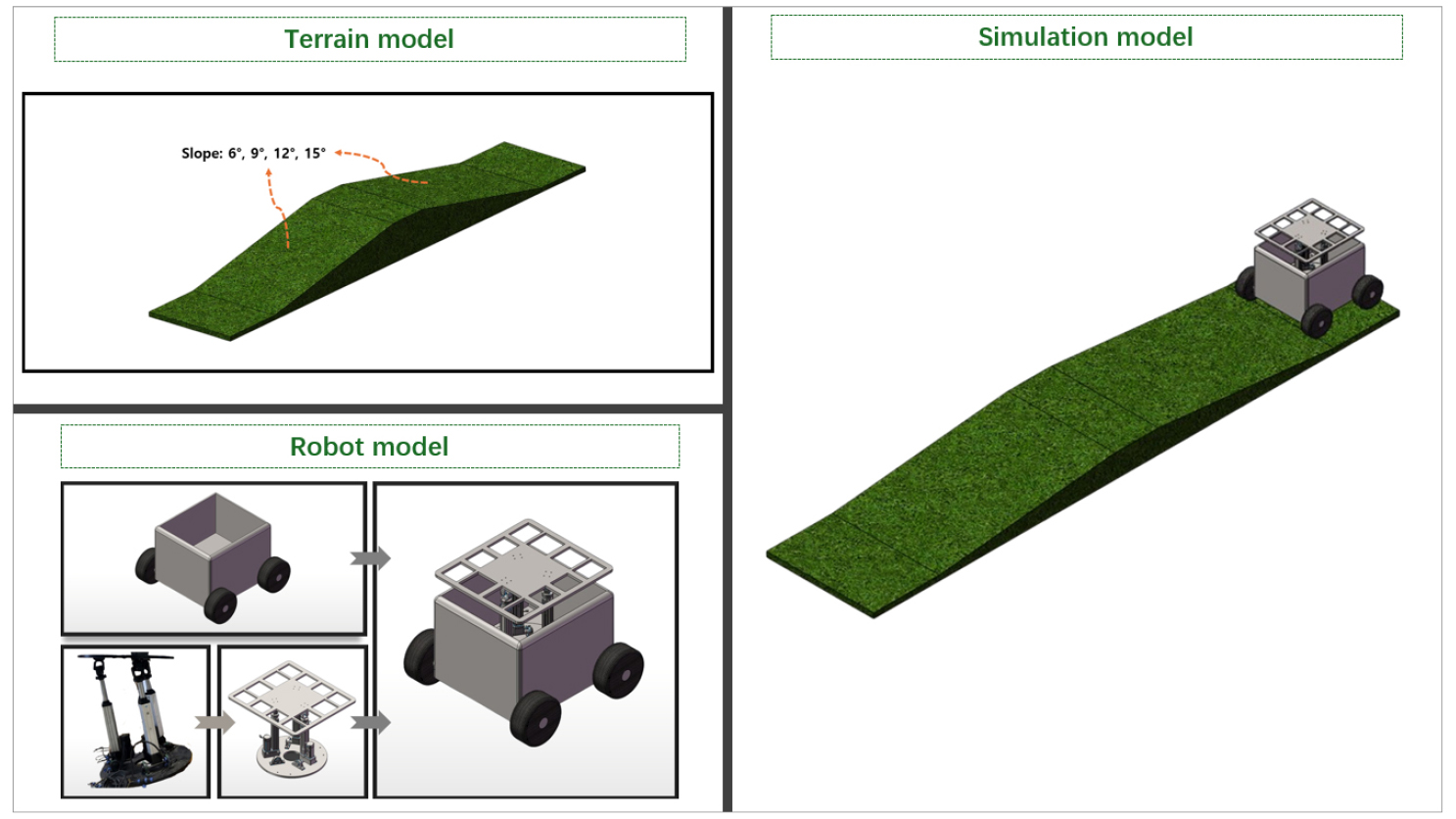
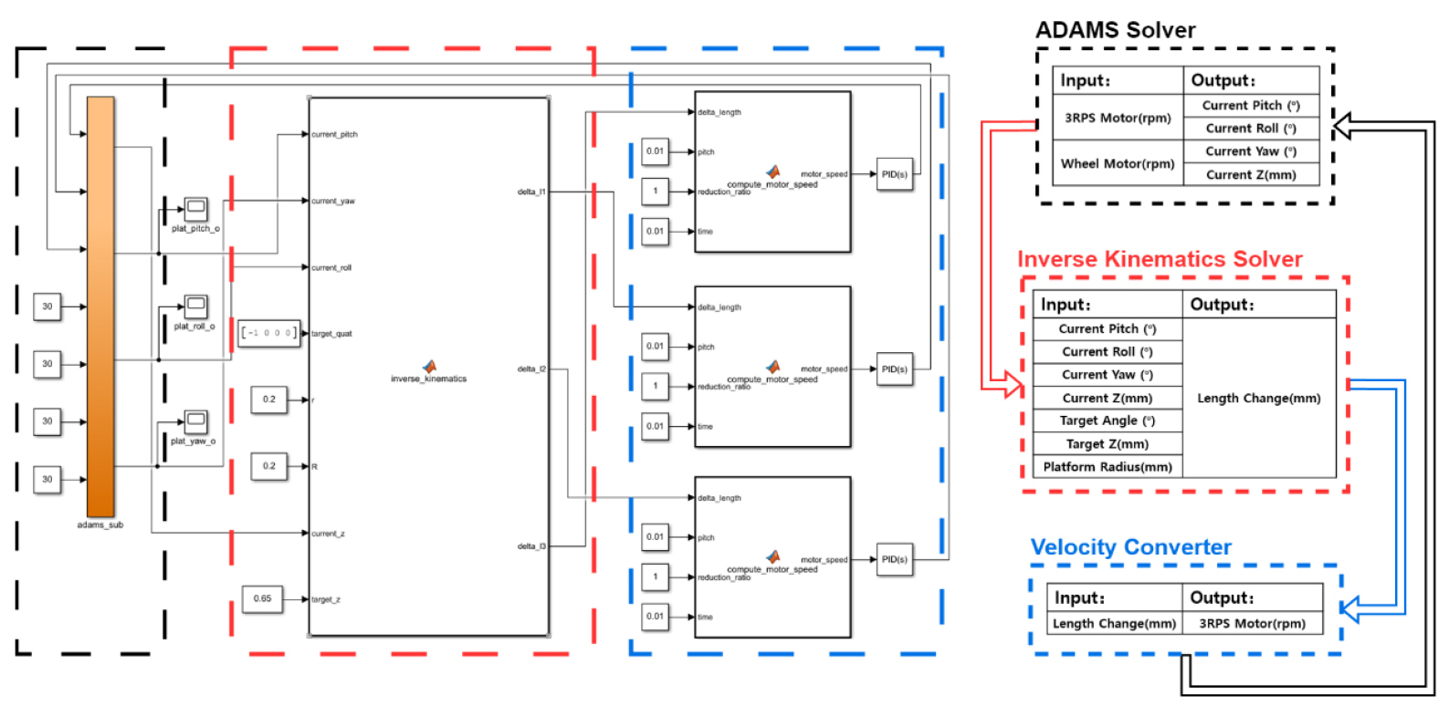
To test the feasibility of the control system, we conducted a simulation using ADAMS (V2016, Mechanical Dynamics Inc., USA) and MATLAB Simulink (2023b, The MathWorks, USA) software. Initially, a 3-RPS mechanism model, set with a mass of 110 kg and a coefficient of friction of 0.5, was designed using SolidWorks (V2020, SOLIDWORKS, France). To evaluate the accuracy of the balance control algorithm, we developed a vehicle model incorporating the 3-RPS system. The balance control algorithm was tested on four simulated terrains, each with a total length of 10 m, featuring slopes of 6°, 9°, 12°, and 15° for both uphill and downhill sections, respectively. Following assembly, the integrated model was imported into ADAMS to conduct detailed kinematic simulations. The systematic process of constructing the simulation environment is illustrated in Fig. 4.
For the development of the simulation controller, MATLAB Simulink was employed. The implementation of the simulation control comprises several key phases. Initially, a constant rotational speed of the wheels on the four-wheeled mobile platform was fed into the ADAMS solver. This solver performs forward kinematics and dynamics simulations within the ADAMS environment to ascertain the real-time pose data of the 3-RPS system. Subsequently, the pose data were input into the inverse kinematics module. In this module, by presetting the platform’s radius and target pose angles, and utilizing inverse kinematics formulas, the theoretical spatial endpoints of each supporting cylinder were calculated, deriving the target lengths of the cylinders required to achieve a balanced state.
To ensure the feasibility of control implementation, the simulation control strategy includes converting the cylinder length variations () into motor speed as shown in Eq. 10.
This conversion was executed in a velocity converter, where by setting the control frequency (), an accurate conversion from the linear speed of the cylinders to the rotational speed () of the motors was achieved. Relevant parameters include the pitch () and radius () of the cylinders.
Upon completing this conversion, the motor speeds were fed back to the ADAMS solver to adjust the cylinder lengths, dynamically updating the platform’s pose. A detailed illustration of the entire simulation control process is included in Fig. 5. This process ensures the precision and efficiency of pose control within the simulation environment.
In the simulated environment, we conducted simulations on the control algorithm. Initially, without activating the balance control system, the mobile robot model traversed the terrain models at a travel speed of 0.5 m s-1. During this phase, we measured the roll and pitch angles of the cargo platform. Next, the mobile robot model traveled the same terrain model with the balance control system activated. The unbalanced angles of the robot platform were continuously monitored, and the balance control system adjusted the posture of the cargo platform to maintain levelness. We assessed the balance error by measuring the platform angles during the test with the balance control system activated.
Outdoor Experiment
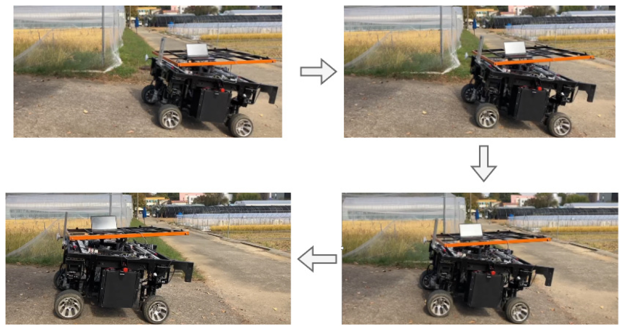
To evaluate the performance of the balance control system, we conducted experiments at two outdoor locations. Initially, an uphill test was performed on a steep slope road with a maximum gradient of approximately 12° and a length of about 3 m, where the mobile robot traveled at a speed of 0.5 m s-1. The roll and pitch angles were tested both with the balance control system deactivated and activated. In balance control mode, the system continuously monitored the imbalance angle of the robot platform and adjusted the posture of the cargo platform to maintain it level, as illustrated in Fig. 6.
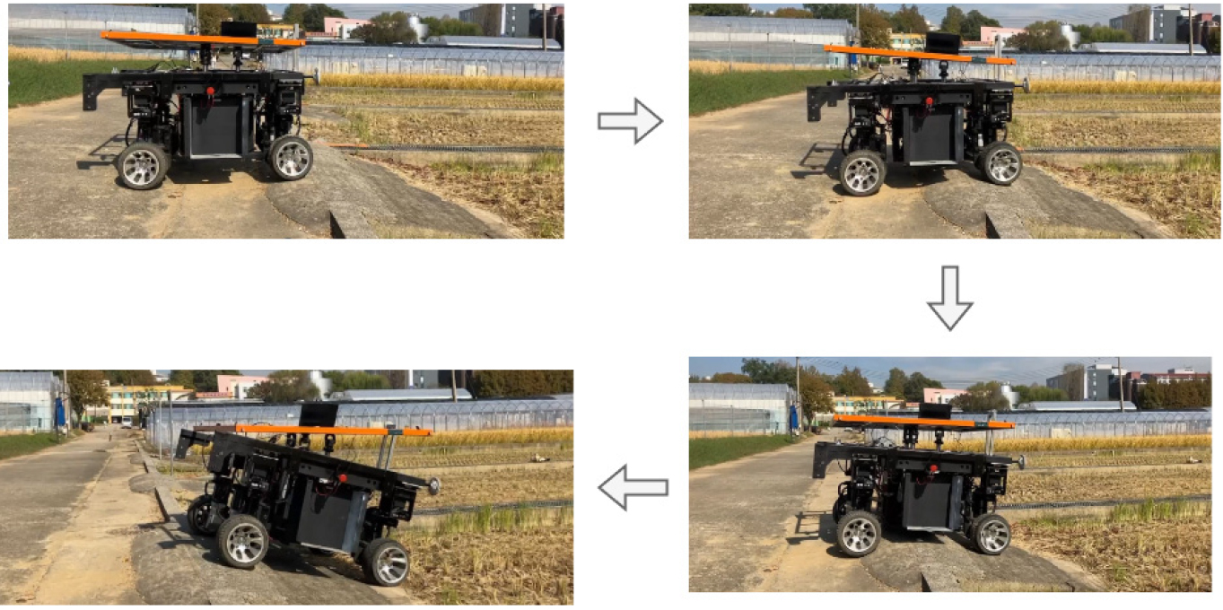
Subsequently, we tested the performance of the balance control system on a challenging terrain at the entrance of a paddy field, which featured both a brief uphill and a sudden downhill, with a maximum bump angle of approximately 15° and a length of about 5 m. Similar to the uphill test, the robot traveled at a speed of 0.5 m s-1, and the system was tested with the balance control turned off and on, traveling twice in each condition. In the tests where the balance control system was activated, the system dynamically adjusted the posture of the cargo platform to ensure it remained level, as shown in Fig. 7.
Result
Simulation Test
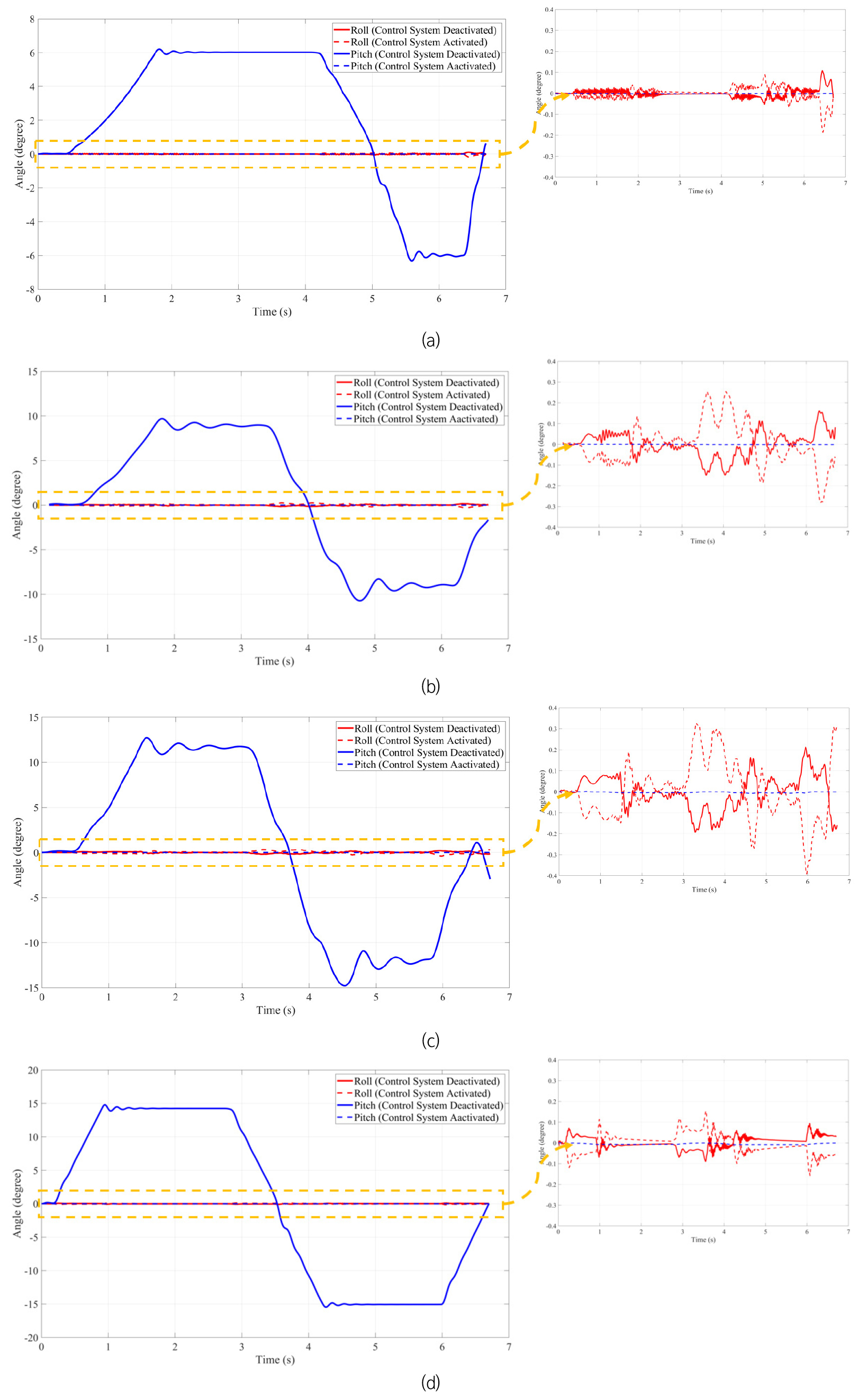
The simulation results are shown in Table 1. Since the terrain model was designed with changes only in the pitch angle, the roll angles remained near 0° with the control system both deactivated and activated. The pitch angles matched the terrain slopes (6°, 9°, 12°, and 15°) with the control system deactivated and then maintained near level after activating the balance control system. The variations of the roll and pitch angle over time at the four terrain slopes are shown in Fig. 8.
Table 1.
Roll and pitch angles in simulation tests at terrain slopes of 6°, 9°, 12°, and 15°.
| Terrain Slope | |||||||||
| 6° | 9° | 12° | 15° | ||||||
| Deact.* | Act.** | Deact. | Act. | Deact. | Act. | Deact. | Act. | ||
|
Roll (°) | Max. | 0.107 | 0.082 | 0.161 | 0.254 | 0.212 | 0.327 | 0.094 | 0.148 |
| Avg. | 0.012 | 0.021 | 0.040 | 0.070 | 0.061 | 0.106 | 0.022 | 0.112 | |
|
Pitch (°) | Max. | 6.201 | 0.001 | 9.690 | 0.001 | 12.700 | 0.007 | 14.800 | 0.008 |
| Avg. | 4.220 | 0.008 | 6.160 | 0.007 | 8.150 | 0.005 | 11.200 | 0.005 | |
Indoor Static Test
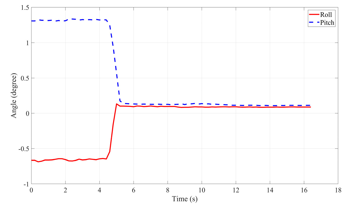
We conducted a static test for the cargo balance control system on the mobile robot while it was stationary indoors to analyze the response capability of the 3-RPS system to single-frame angular data. Initially, we manually controlled the cargo platform to reach specific angles. To simulate and analyze the platform’s single-frame angle control capability during dynamic transportation, we set the initial pitch and roll angles at 1.34° and 0.69°, respectively. Given that angle changes in real outdoor environments for robots are gradual rather than sudden, we chose these angles for the test. Once the angles were set, we activated the angle balance control system. The angular changes of the entire platform are illustrated in Fig. 9. After automatic adjustments, both the pitch and roll angles were leveled to 0.08°, with the adjustment process taking 1.1 s.
Outdoor Dynamic Test in Uphill Road
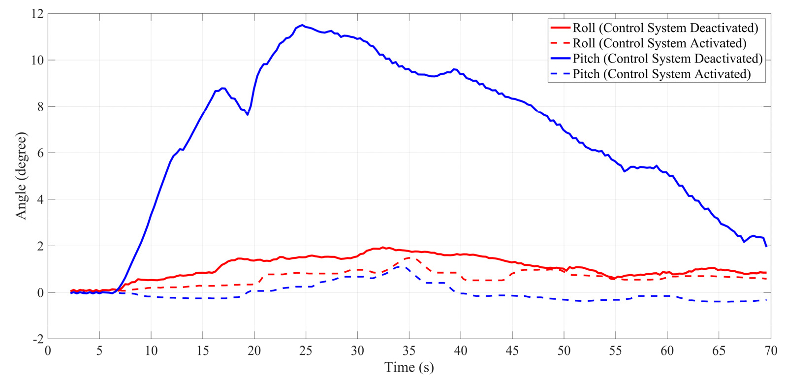
The roll and pitch angles over time with the balance control system activated and deactivated on an uphill road are shown in Fig. 10. Prior to activating the balance feature, the maximum pitch and roll angles were 11.53° and 1.95°, respectively, and the average angles were 6.51° and 1.06°, respectively. After activation of the balance control system, these angles significantly reduced, with maximum pitch and roll angles of 1.09° and 1.40°, respectively, and average angles of 0.28° and 0.61°, respectively. These results demonstrate the effectiveness of the balance control system in significantly reducing platform tilt and maintaining near-level operation.
Outdoor Dynamic Test in Bump-Downhill Road
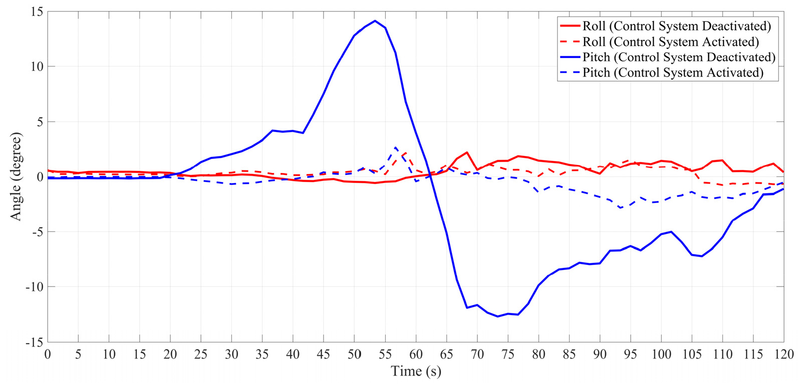
Fig. 11 shows the roll and pitch angles over time with the balance control system deactivated and activated on a bumpy downhill road. Before activating the balance function, the maximum pitch and roll angles were 14.13° and 2.42°, respectively, with average angles of 6.92° and 0.88°. After activation, these errors were substantially reduced, with maximum pitch and roll angle errors decreasing to 2.85° and 2.21°, respectively, and average angles to 1.12° and 0.64°. This indicates that our system significantly minimizes tilt and maintains a near-level posture during motion.
Limitation and Future Work
In this study, we primarily focused on the balance of pitch angles. Testing roll angles requires positioning the robot laterally on a slope. We plan to test the balance control system in environments where both roll and pitch angles are present in the future.
During our experiments, we observed that when there were abrupt changes in the slope, the angle of the robot using the 3-RPS system would suddenly change significantly. This phenomenon indicates that the response frequency and robustness of the system need further improvement to better adapt to such abrupt angle changes. To address this requirement, we plan to integrate an adaptive parameter adjustment feature into the PID control system to enhance the system’s responsiveness and adaptability.
Moreover, considering safety, all tests were conducted under no-load conditions. To further validate the performance and stability of the system under different working conditions, future tests will include experiments with varying load weights. Through these tests, we aim to obtain a more comprehensive evaluation of the system’s performance to guide subsequent design and optimization efforts.
Conclusion
This study successfully developed a balance control system for the cargo platform of a mobile robot based on 3-RPS parallel mechanisms. We validated the feasibility of the control system through combined simulations in ADAMS and MATLAB Simulink and implemented the system in real environments using an IMU sensor. In dynamic outdoor environments, the control system maintained the pitch angles of the cargo platform at less than 1.09° on a maximum uphill slope of 11.53° and at less than 2.85° on a maximum downhill slope of 14.13°.
In the future, to achieve a more comprehensive evaluation of system performance, we plan to conduct tests in environments that simultaneously exhibit both pitch and roll angles. Additionally, the system will be assessed under varying load conditions to capture its robustness and operational efficacy across different scenarios.
